Valve Controller


Description
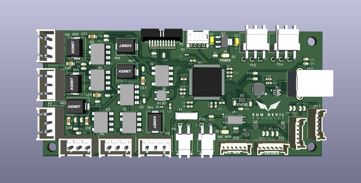
The liquid engine's valve controller contains the processor responsible for managing valve actuation commands issued by the liquid engine controller. The board contains opto-isolated solid state relays for solenoid actuation and a Pulse Width Modulation interface for issuing stepper motor commands which initiate actuation of the liquid engine's main propellant valves. The board is powered from the 5V buck converter on the engine controller, which is also used to power the photogate sensors used for valve position calibration. In order to allow the controller to know the true actuation state of the solenoids in the event of a power failure, the board also contains an AC power supply monitoring circuit which asserts an MCU signal when AC power is available for solenoid actuation.
Technical Specifications
Microcontroller: STM32H750VBT6
Processor: ARM Cortex-M7
Maximum Clock Speed: 480 MHz
Memory: 128 kB Flash, 1MB RAM
Maximum Supply Voltage: 30V
Maximum Current Draw: 1A
Actuators: 6 AC Solenoid Drivers, 2 Stepper Motor PWM
interfaces
Connectivity: UART, USB
Sensors: 2 Photogates, 2 Encoders
Sources and Documentation
Schematic: Valve-Controller-Schematic.pdf
Design Doc: Valve-Controller.pdf
PCB Design Files: GitHub
Firmware Source Code: GitHub
Bill of Materials: BOM.pdf, BOM.xlsx
3D Model: Valve-Controller.step
Version History
Version 3.1

Updates:
- Fixed Photogate connector pinouts to allow straight wiring from photogate connector to valve controller connector
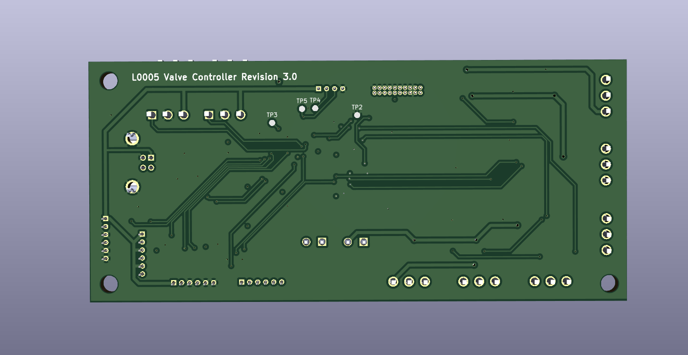
Version 3.0

Updates:
- Used in hotfire tests, 4/27/2023 and 5/12/2023
- Added USB interface
- Changed pulse interface to 5V open drain logic
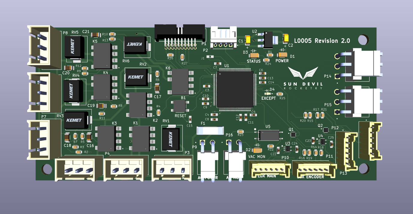
Version 2.0

Updates:
- Switched microcontroller from NXP M4 to STM32 M7
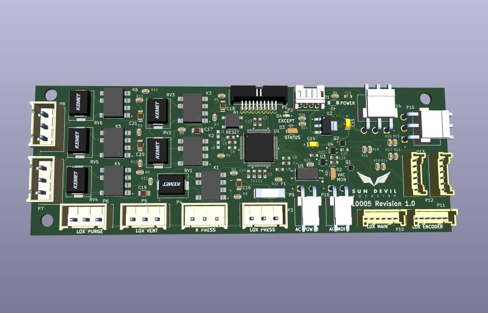
Version 1.0

Updates:
- Initial version
- Implemented solenoid solid state relay circuits
- Implemented servo motor pulse interface