Liquid Engine Controller
Description
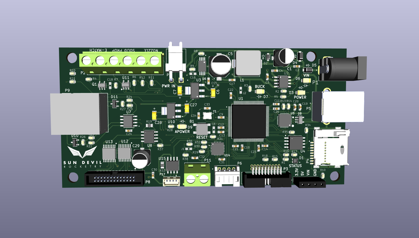
The Liquid Engine Controller is the main embedded processor of Sun Devil Rocketry's Liquid Engine. As the brains of the engine, the controller is responsible for executing propellant feed sequences semi-autonomously, logging sensor data, and transmitting engine telemetry. The controller is equipped with an STM32 ARM Cortex M7 processor and 4Mb of external flash for data logging. The board includes a micro-SD card jack for easy access to the logged data. The board includes many power sources for flexible use of the controller during testing and normal operation. These include a 12V power jack, a USB Type B connector, and a 2-pin male pin header. The board includes short circuit protection on the main power rail and regulates the multiplexed supply to 5V and 3.3V with a buck converter and linear regulator (LDO) respectively. The board interfaces with a PC through either the USB port or the 8-pin telemetry connector, which allows wireless transceiver modules with either a UART or SPI interface to be connected. The screw terminals on the board connect to the ignition circuitry. An e-match is used to initiate combustion, and two continuity wires are used to provide the controller feedback on the ignition state. The ignition current is routed through an additional screw terminal which serves as a safety/arming switch. The board interfaces with all of the engine sensors, including eight pressure transducers, a thermocouple, and a load cell. The pressure transducer outputs are amplified with a programmable-gain instrumentation amplifier, which allows for up to 256 calibration settings. The thermocouple output is processed using a cold-junction compensation IC. Additionally, the board includes a reset button and several LEDs for visual indication of power and firmware status.
Technical Specifications
Microcontroller: STM32H750VBT6
Processor: ARM Cortex-M7
Maximum Clock Speed: 480 MHz
Memory: 128 kB Flash, 1MB RAM, 4 Mb External Flash, 1 SD Card
Maximum Supply Voltage: 30V
Maximum Current Draw: 1A
Sensors: 8 pressure transducers, 1 load cell, 1 thermocouple
Connectivity: USB, RS485/Ethernet, UART Valve
Control Interface
Sources and Documentation
Schematic: Engine-Controller-Schematic.pdf
Design Doc: Engine-Controller.pdf
PCB Design Files: GitHub
Firmware Source Code: GitHub
Bill of Materials: BOM.pdf, BOM.xlsx
3D Model: Engine-Controller_Rev5_1.step
Media
RGB LED
Ignition Test
Version History
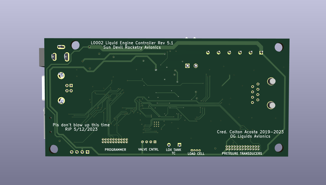
Version 5.1

Updates:
- Added RS485/Ethernet telemetry interface
- Removed switch screw terminals
- Fixed valve controller connector pinouts
- Moved screw terminal labels to top of board
- Removed wireless interface connector
Version 5.0
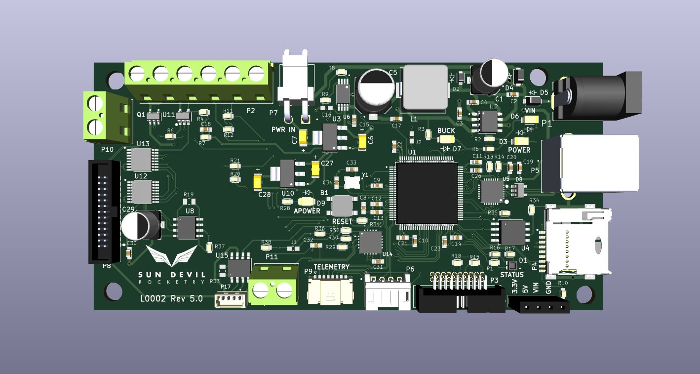
Updates:
- Used in hotfire tests, 4/27/2023 and 5/12/2023
- Removed unnecessary programmable gain circuity for pressure transducers
- Added support for four 0-5V output pressure transducers
- Switched thermocouple connector to screw terminal
- Fixed thermocouple open/short circuit detection circuits
- Added USB power detection
Version 4.0
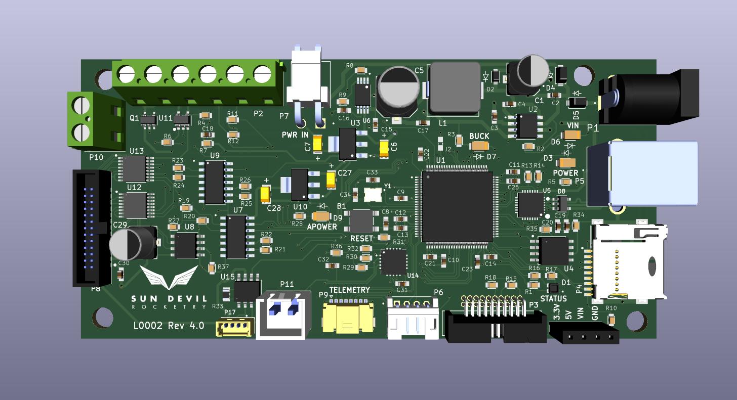
Updates:
- First hotfire ready revision
- Added pressure transducer ports/amplifier
- Added thermocouple port and IC
- Added load cell port and amplifier
- Fixed incorrect pinouts in ignition circuitry
- Added analog 3.3V power supply (LDO)
- Reduced form factor of SWD programmer connector
- Switched SD card from SPI to SDIO/SDMMC interface
- Removed prototyping pin headers
Version 3.0
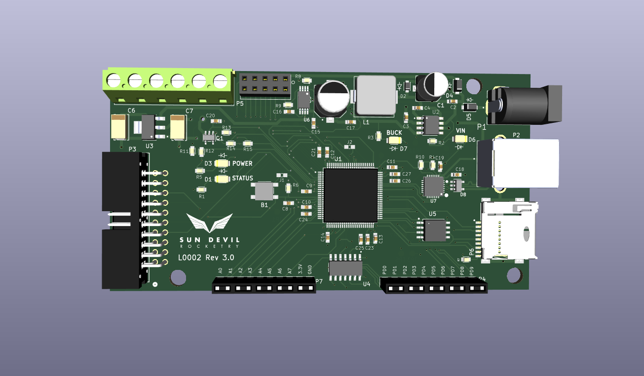
Updates:
- Changed microcontroller from M4 to M7
- Fixed 5V buck converter
- Added ignition circuitry
- Added USB data traces
- Added USB-to-UART bridge for USB connectivity
- Added standard 20 pin SWD programmer connector for St-Link
- Reduced buck converter cap form factors
Version 2.0
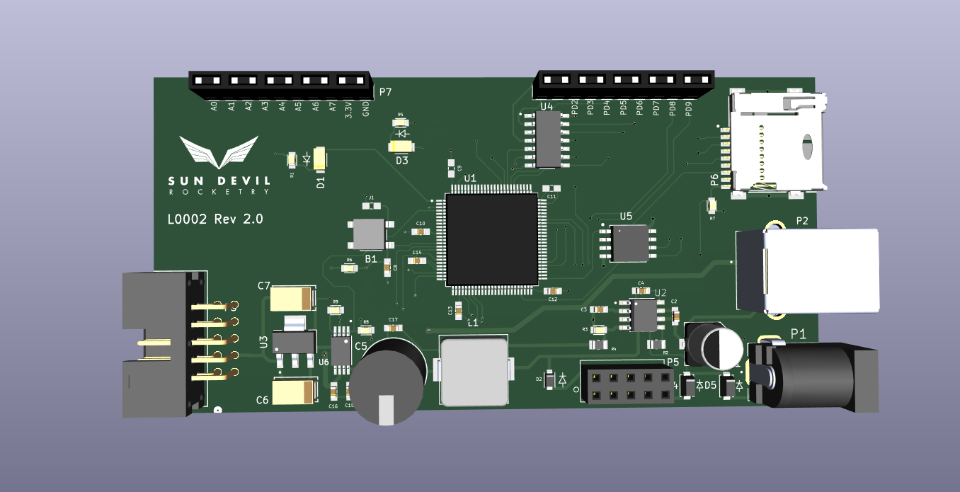
Updates:
- First manufactured design
- Added short circuit protection to 12V barrel jack and VIN header
- Fixed buck converter layout
- Added power supply multiplexor for USB 5V and 12V sources