Liquid Rocket Engine
Project Overview
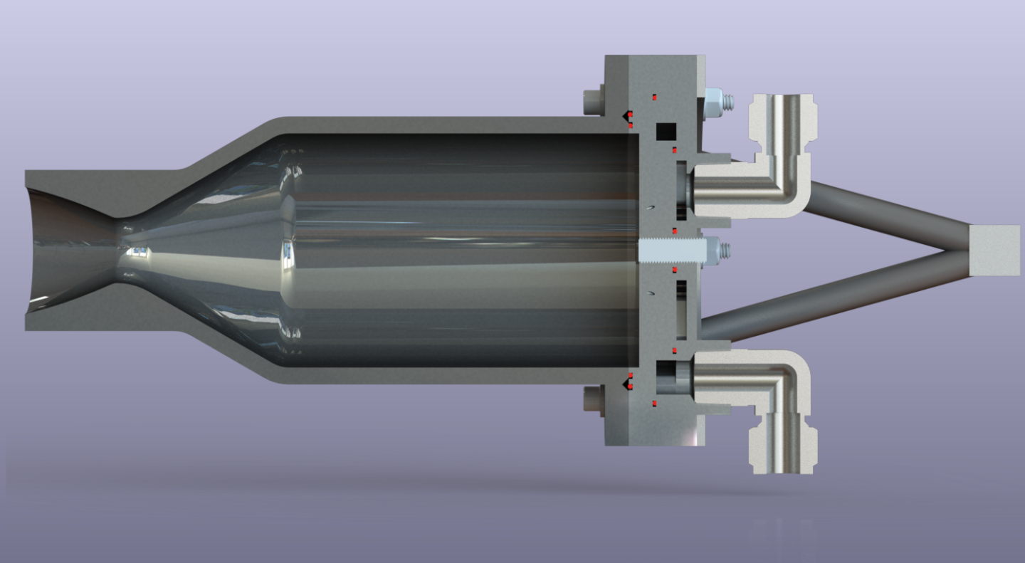
The liquid propulsion team is the largest team within Sun Devil Rocketry, and aims to develop and test ASU's first liquid propellant rocket engine. The project's purpose is to provide undergraduate students at ASU with the opportunity to develop engineering skill sets relevant to the modern aerospace industry through the application of knowledge obtained in the classroom to the design and development of a rocket engine. The team has designed and manufactured a number of custom pieces of hardware, including an injector, a radiatively-cooled combustion chamber, several custom avionics boards, a component testing apparatus, and a structural test stand. Each piece of custom equipment has gone through multiple design iterations and dozens of hours of computational analysis. The team is organized into five different sub-teams, including the propulsion, plumbing, avionics, structures, and test operations sub-teams. The project has been in development for three years, has been led by three different generations of Sun Devil Rocketry engineers, and to date over 50 students at ASU have contributed to the project.
Personal Involvement
I have been involved in the liquids project since its beginning in the fall of 2019, and have held two different leadership roles within the team. For the last two years I have led the avionics subteam, and I served as overall team lead during the 2021-2022 school year. As liquids team lead, I facilitated development of the project by holding weekly team meetings, scheduling safety trainings, managing university relations, and writing budgeting proposals. I pushed the team to progress from the design phase to the testing and rapid-prototyping phase after Sun Devil Rocketry regained access to the student organization shop space after a year of virtual work during the peak of the COVID pandemic. With respect to technical contributions, I have architected the engine's entire avionics system from the user interface to the engine control circuitry. Currently, the avionics system consists of a central engine controller, a valve-controller, six solenoids, two servo-actuated ball valves, two optoelectronic photogate sensors, a ground-station computer, and a custom user interface application. For more information on the specifics of these avionics systems, see their designated pages here.
Engine Specifications
Engine Thrust: 405 lbf
Thrust Duration: 5 seconds
Chamber Pressure: 250 psig
Propellants: Liquid Oxygen and Kerosene
Cooling: Film Cooling
Sources and Documentation
Plumbing and Instrumentation Diagram: PandID.png
2020 AIAA Propulsion and Energy Paper: AIAA_Paper.pdf
2020 AIAA Propulsion and Energy Presentation: AIAA_Presentation.pdf
Website Page: link
Propulsion
The propulsion subteam is responsible for the design of the engine's combustion chamber and injector. The team mainly performs computational fluid dynamics simulations to characterize the engine's combustion, thermodynamics, mixing, and structural stability. Analyses previously performed by the team have included the following:
- NASA CEA simulations to characterize combustion enthalpy and steady-state burn temperature from choice of propellants, Oxidizer-to-Fuel (OF) ratio, and chamber pressure.
- Ansys CFD simulations to characterize the steady-state mixing and atomization properties of the injector and combustion chamber
- Ansys static-structural and thermal simulations to characterize the engine's cooling and structural integrity during combustion.
Currently the team is working to manufacture the combustion chamber and ground the computational results with real-world data obtained from testing the injector and combustion chamber using Sun Devil Rocketry's component testing apparatus.
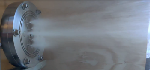
Liquid Engine Injector Test
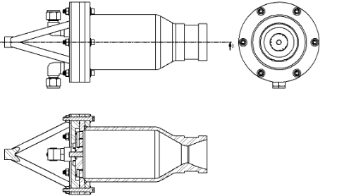
Combustion Chamber Engineering Drawing
Plumbing
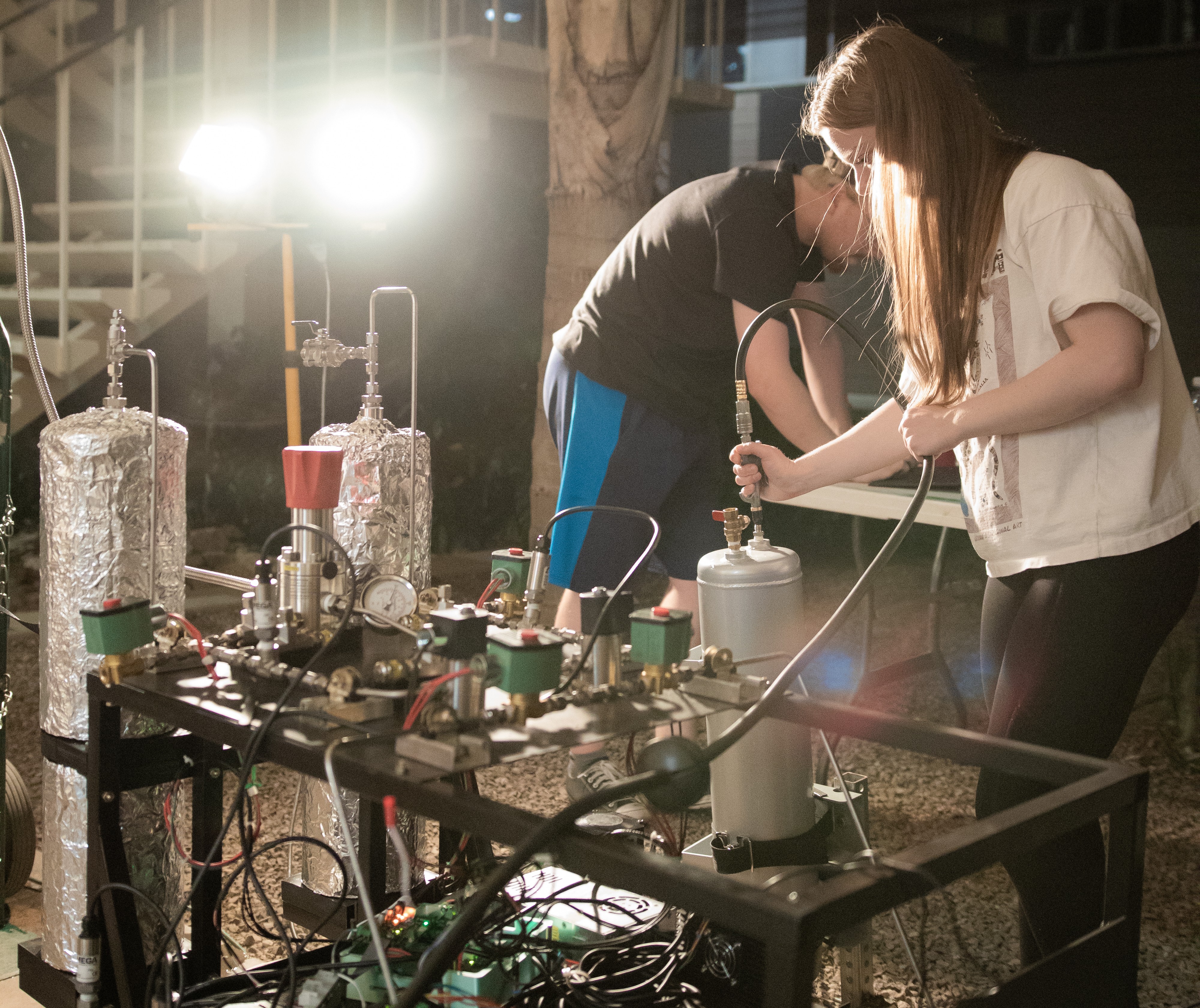
The plumbing team is responsible for the design and development of the liquid engine's pressure-fed propellant feed system. The plumbing system delivers the kerosene and liquid oxygen propellants from their tanks to the combustion chamber to be ignited. The plumbing system also controls the pressurization system which pressurizes propellants with gaseous nitrogen and purges residual propellant from the system after combustion. Analysis of the plumbing system mainly consists of pressure drop and thermodynamic state calculations. The plumbing system consists of ball valves, solenoids, check valves, relief valves, tanks, pressure transducers, thermocouples, pressure regulators, orifices, pressure gauges, pipes and fittings.
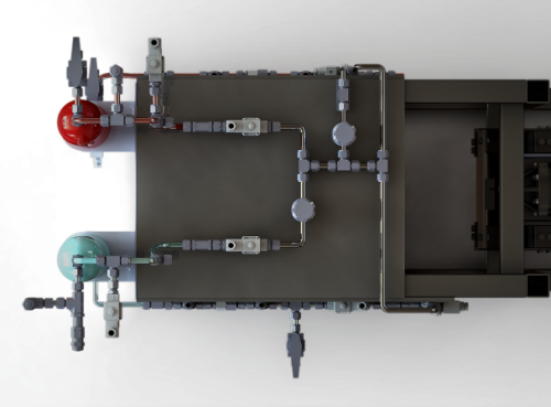
Liquid Engine Plumbing
Test Operations
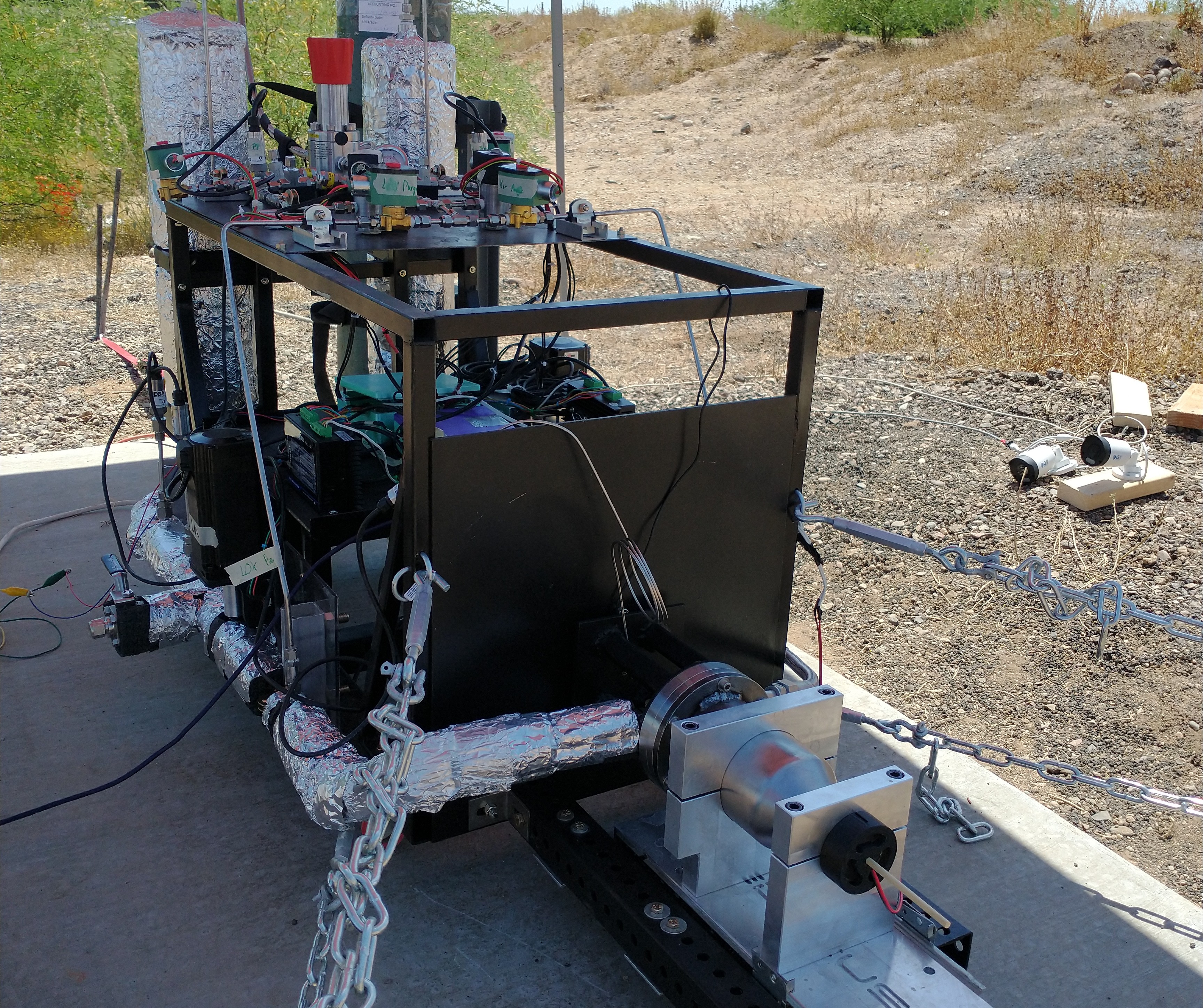
Development of the liquid rocket engine is driven by testing and experimental characterization of engine components. The test operations team is responsible for designing and conducting component tests to verify proper operation of engine components and to inform future design and development. The test operations team has developed a component testing apparatus shown in the image to the right which allows SDR engineers to collect data on the flow characteristics of individual engine components. Tests performed by the test operations team have included pressure transducer calibration, orifice flow meter calibration, injector pressure drop characterization, and injector mixing performance characterization. The team is currently working to design a cryogenic subsystem of the testing apparatus to allow the team to test the performance of plumbing components at cryogenic temperatures using liquid nitrogen.
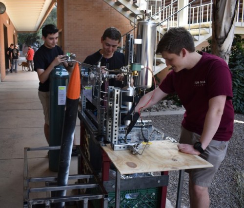
Component Test Apparatus
Avionics
In order to control the engine in an efficient and safe manner, a semi-autonomous avionics system is used. The avionics team is responsible for the design of the engine controls, data acquisition systems, and user interface. The system consists of the following components:
- A primary controller for implementing engine sequencing and logging data.
- A valve controller for managing actuation commands, containing solenoid drive electronics and servo motor control interfaces.
- Two servo-actuators for main valve control, containing custom mechanical coupling and optoelectronic sensors for startup calibration.
- A raspberry-pi based ground station computer used by test engineers to control and monitor the engine remotely.
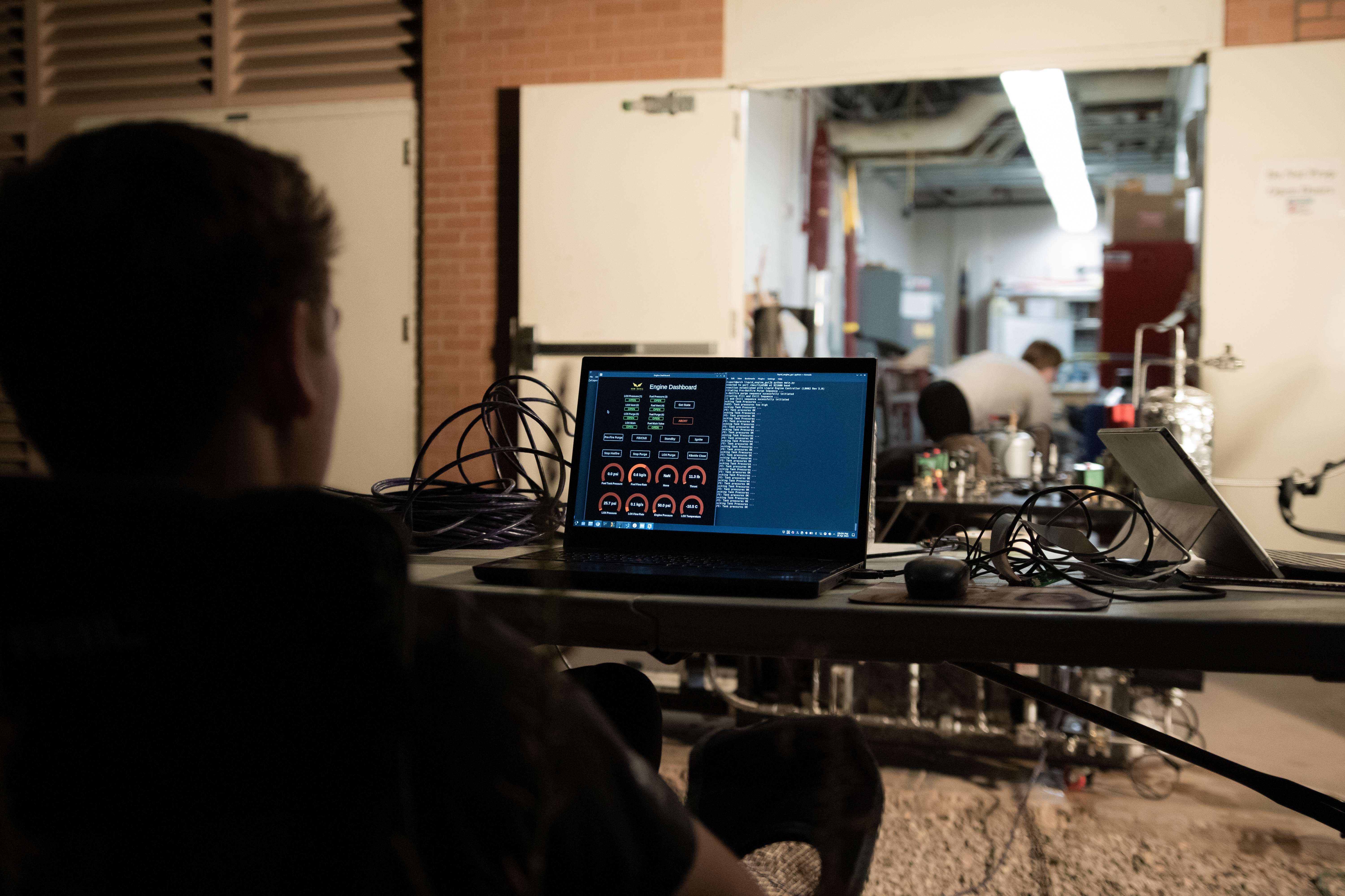
- A Tk-based user interface application with engine controls, sensor gauges, and a complete engine display.
All of the avionics controllers are designed from scratch using PCB software, and are manufactured by hand in-house. Embedded software is written in C to run on ARM Cortex-M microprocessors, and PC software is written in Python. The team is currently working to test the engine control circuitry and develop subsystem APIs for each component of hardware needed by the application software.
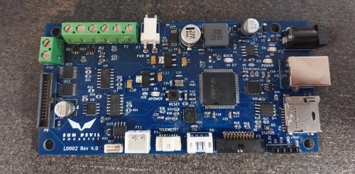
Engine Controller
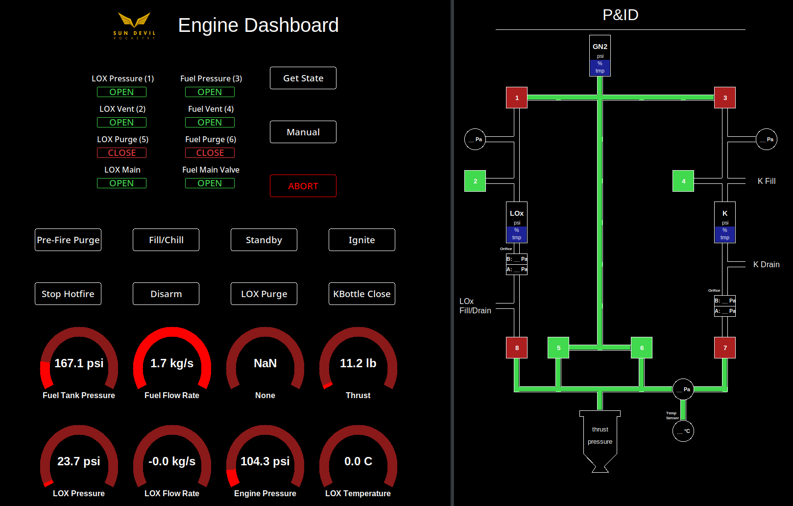
Engine User Interface Application
Structures
The structures team is responsible for the design of the static test stand used to restrain the engine during a hotfire test. The team performs Ansys static structural simulations to determine weak points of the structure with large stress concentrations and verify that the structure will not yield under the load of the engine thrust or the weight of the plumbing system. The structures team is currently working to weld the test stand together and drill the necessary mounting holes to attach the avionics tray, restraining hooks, and wheels.
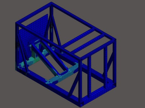
Test Stand Ansys Static Structural Simulation
Media
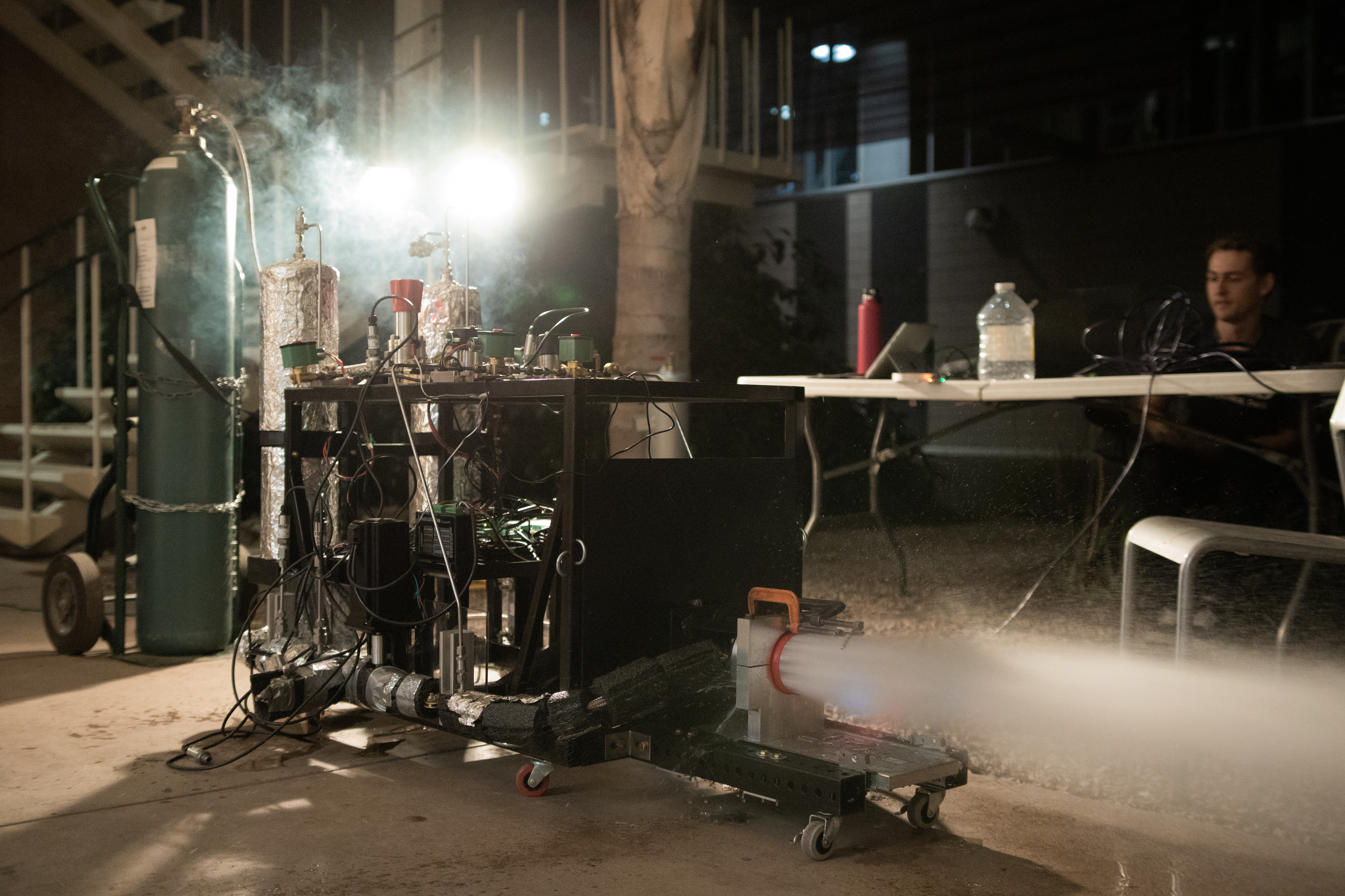
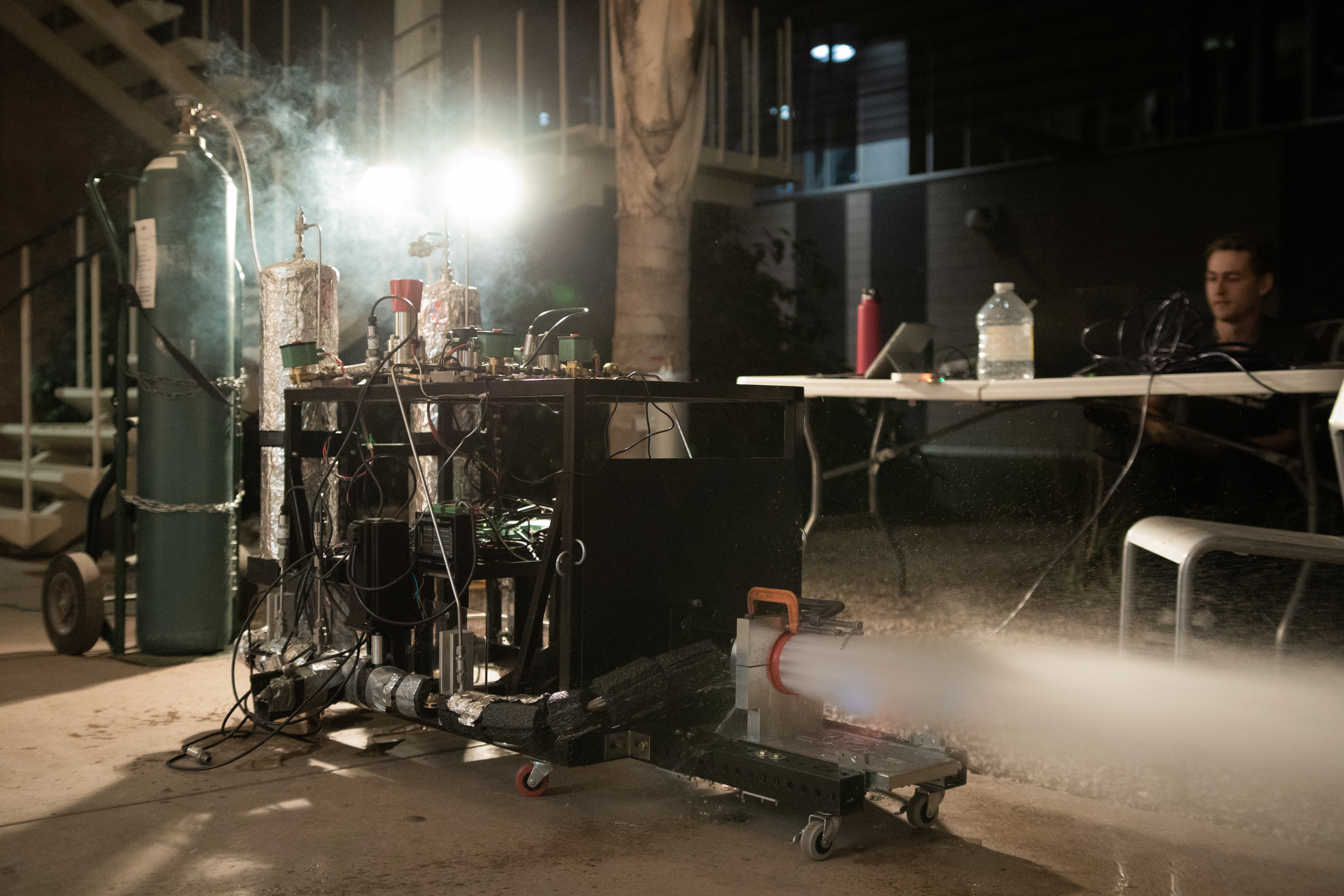
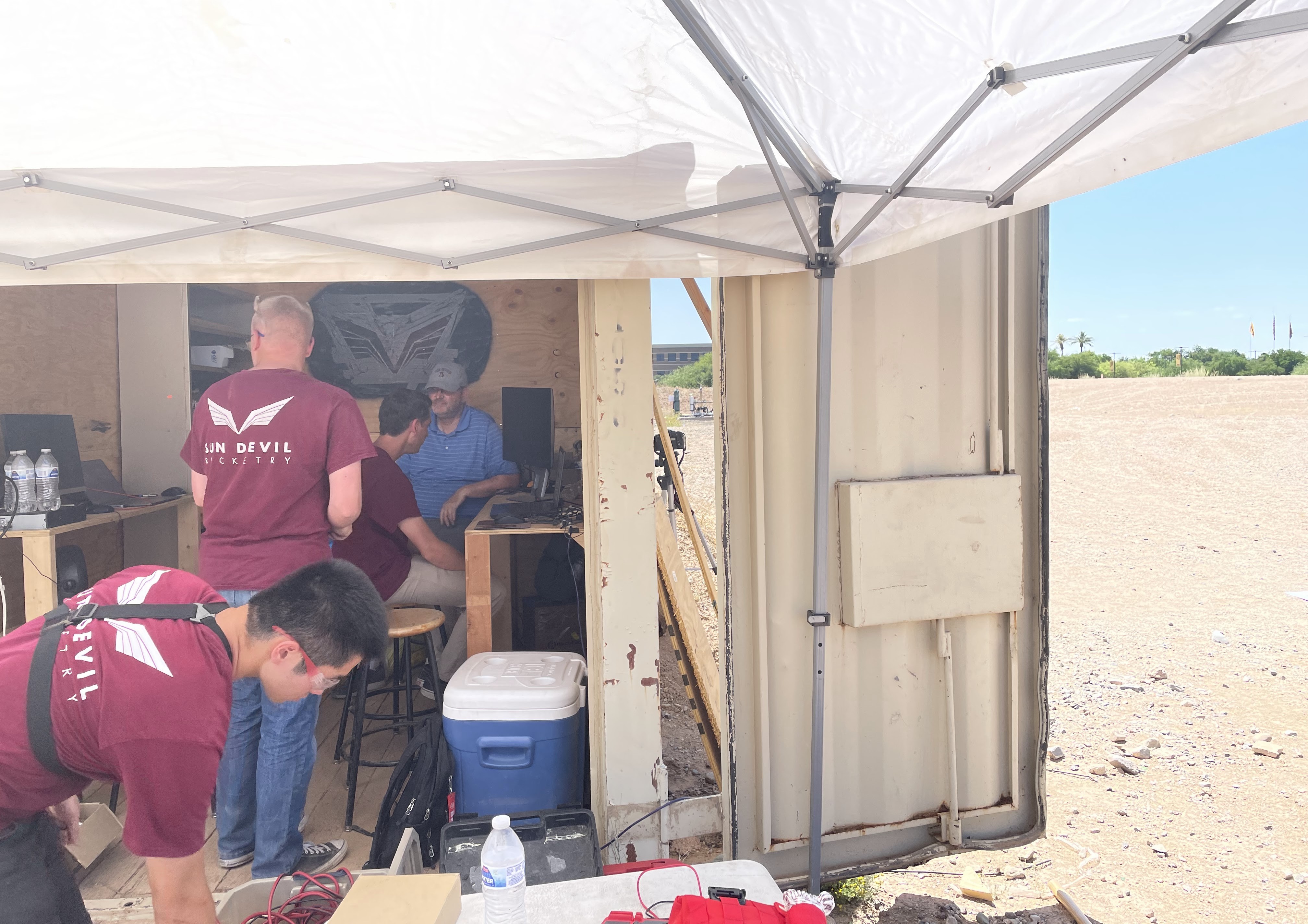
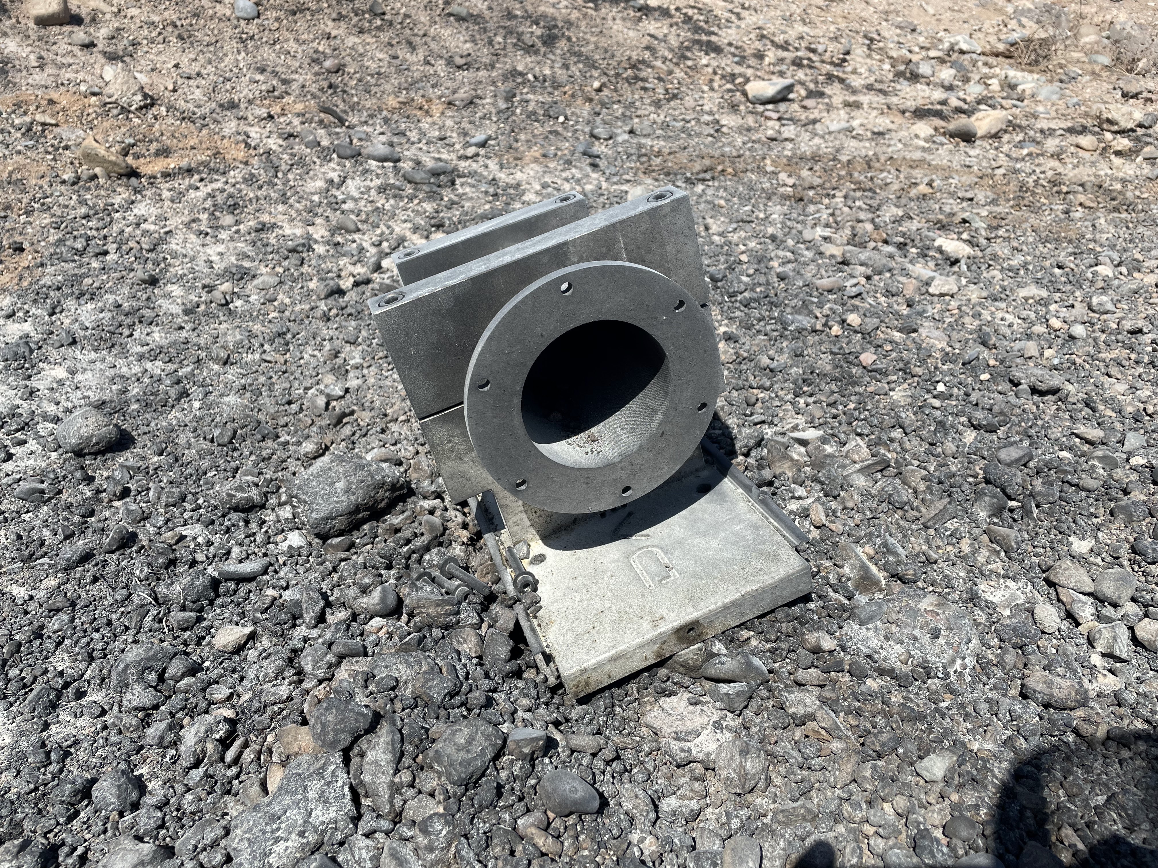
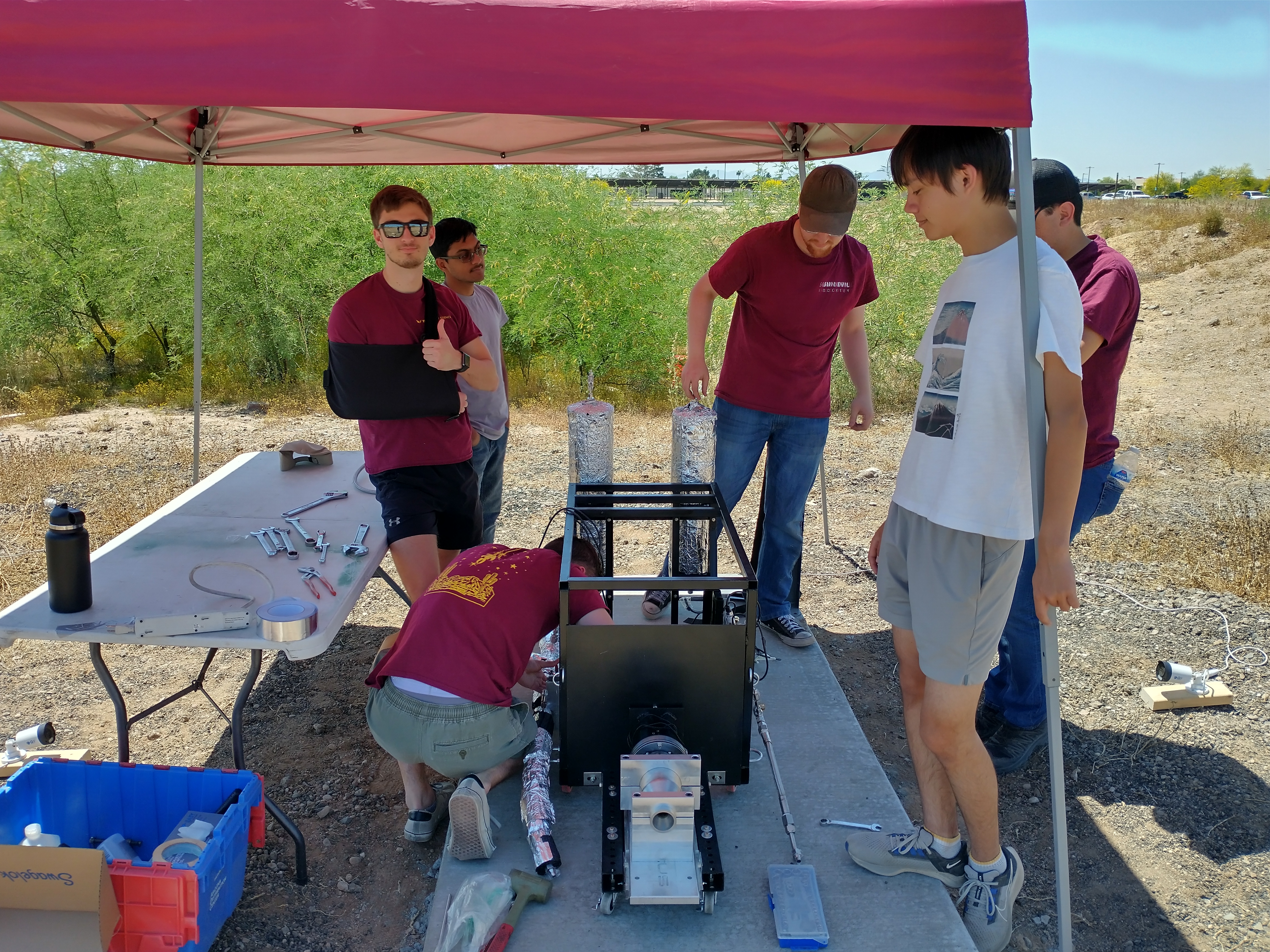
5/12/2023 Hotfire Attempt
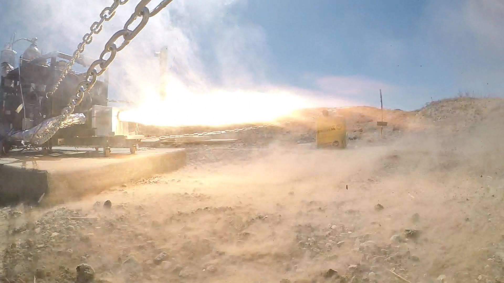
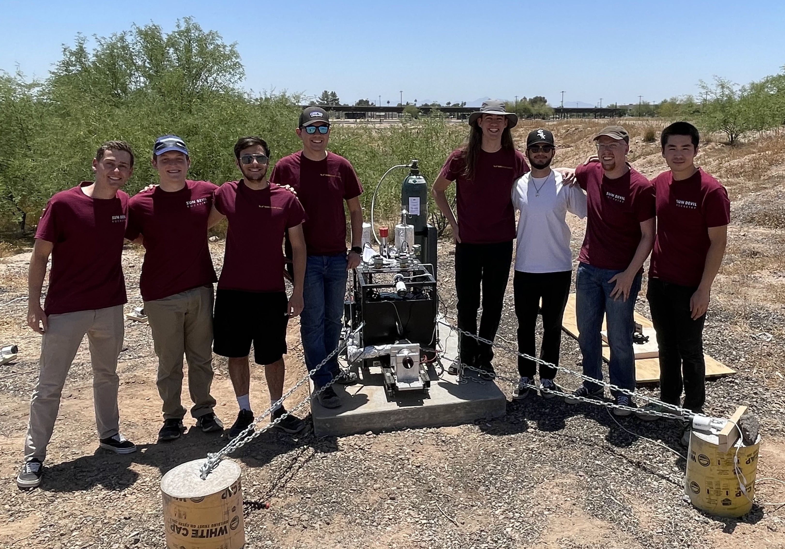
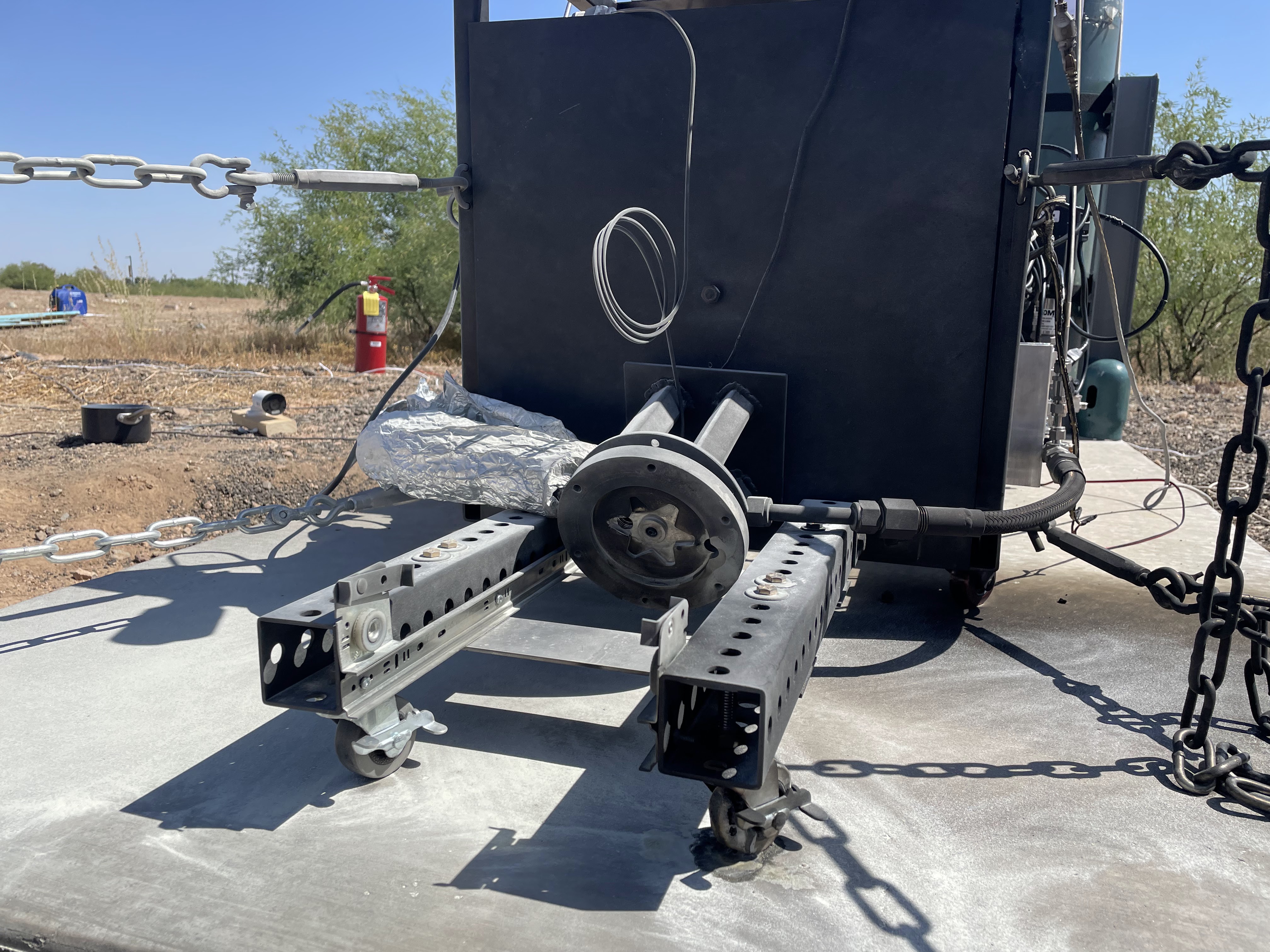
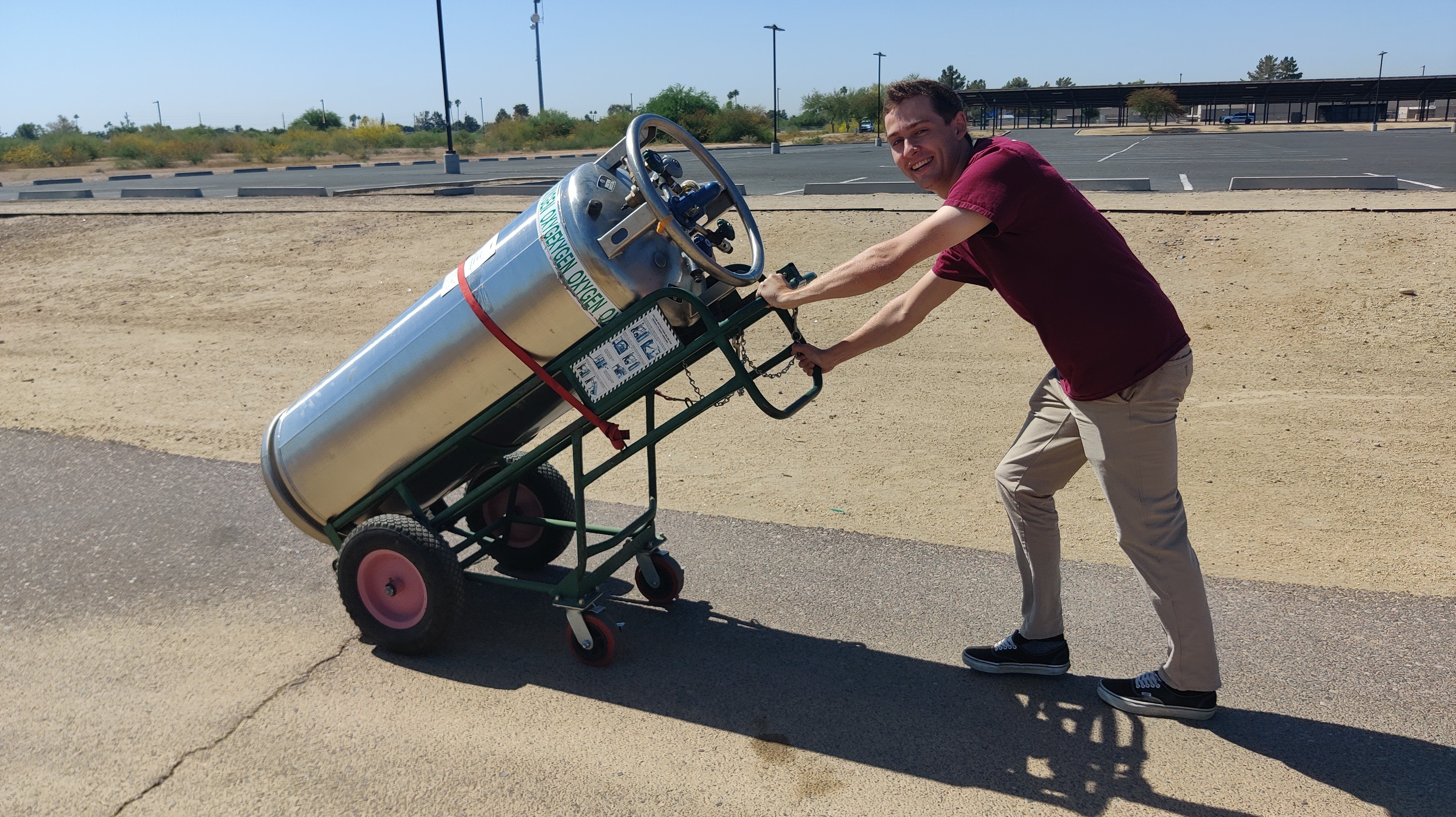
4/27/2023 Hotfire Attempt
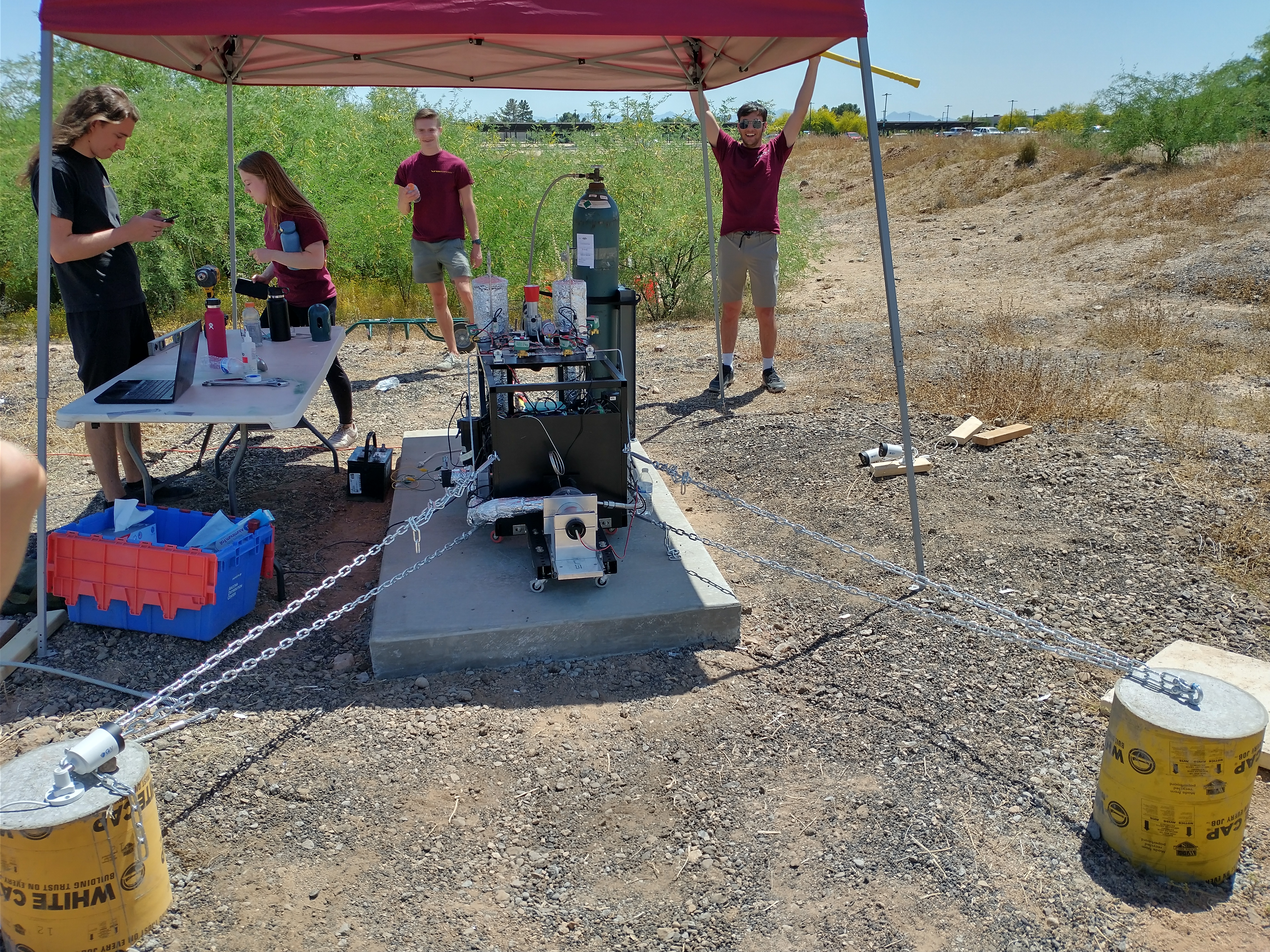
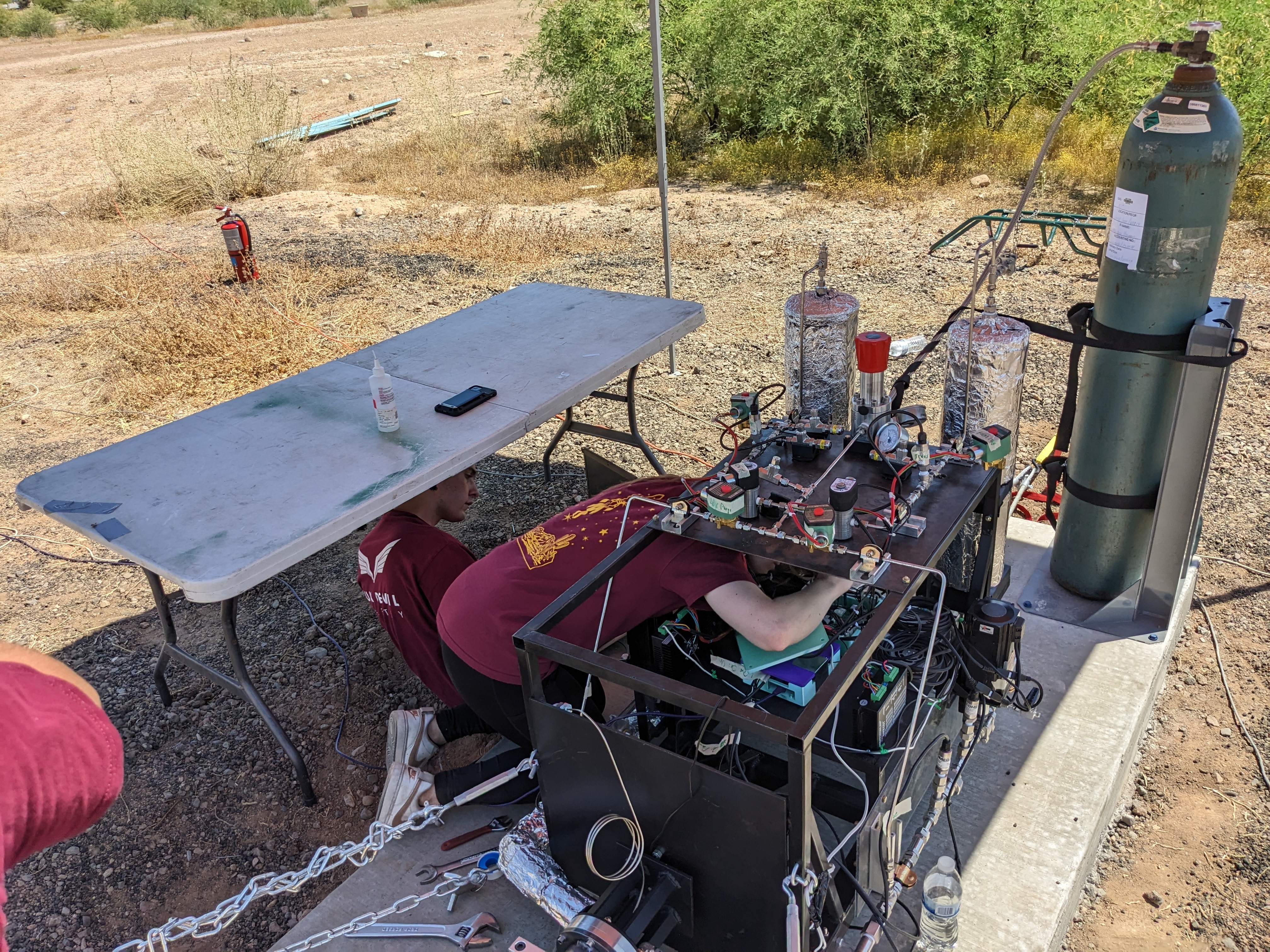
Cold Flow Sequencing Testing
