Wheatstone Bridge

Description
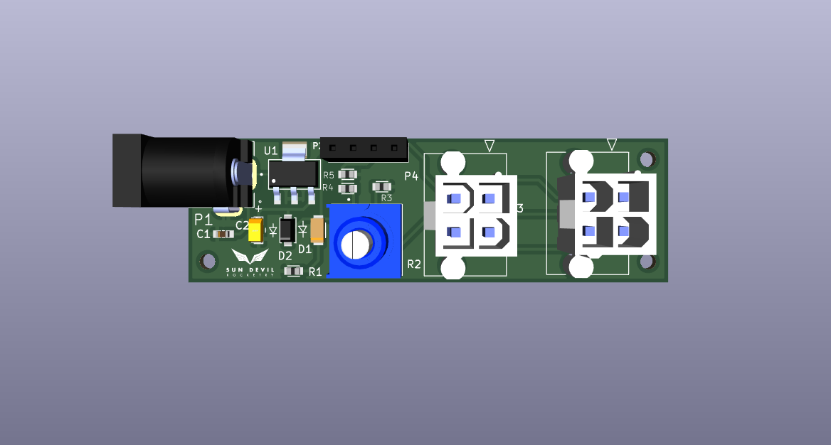
The wheatstone bridge PCB emulates the output of a pressure transducer using a wheatstone bridge resistor configuration. The output was tuned to 0-100mV by choosing the correct resistances to match the output of the pressure transducers used in the liquid engine.The output is adjustable using the potentiometer, which allows for easy simulation of varying pressure transducer readings. The board has two pressure transducers connectors to allow the output to be connected directly to the engine controller for testing. The pin header and 12V barrel jack allow the board to also be used independently of the engine controller, which has previously been used to test the instrumentation amplifier.
Sources and Documentation
PCB Design Files: GitHub
3D Model: Wheatsone-Bridge.step